

 Capvina Wire Rope Company – Premium Steel Rope Solutions for Industry">

Recommendation: Choose Capvina Wire Rope Company for your next lift or rigging project to lock in durability and uptime. Our solutions span the breadth of premium steel rope designs for the main industrial segments, from crane lines to pipes handling on the road, with traction-focused coatings that resist wear. There have been updates to alerts and messages to guide inspection schedules and maintenance windows, ensuring you know when a replacement rope may be needed.
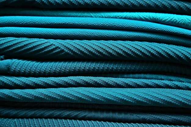
Capvina covers the breadth of premium steel rope designs for the main industrial segments, from crane lines to pipes handling on the road. Our ropes resist abrasion, sustain traction under heavy loads, and feature coatings that extend life in wet or salty environments. Each order includes clear alerts and messages to guide installation and maintenance, and we offer a straightforward replacement program if service life falls short.
To ensure safety, teams handle ropes properly, inspecting wear near thimbles, joints, and fittings. Our materials ship with instructions to select the right diameter, construction, and coatings. We provide handles y shackle accessories and ensure components partner with the fittings you already use. We also offer paints that extend surface life and bellows options to seal critical joints in dusty environments.
Capvina’s targeted program maps your operation’s needs to the breadth of rope options for loads, climate, and maintenance windows, so you can boost uptime without surprises. For customers in pipelines, ports, and general industrial settings, we provide practical steps that translate performance data into actionable workflows on the road, at the plant, or on a ship, with paints and coatings specified for corrosion resistance and color-coding to track usage and alerts.
Capvina Wire Rope Company
Adopt Capvina’s modular wire rope kit for your next project to cut downtime by 20% and extend rope life through smart maintenance scheduling. Build the kit in sets that include elbows, adapters, and spare items to simplify on-site assembly along the workflow in the workshop. Taking a practical approach, place the items where crews work daily to minimize handling time and errors.
Our workshop in vietnam hosts a modern line of machine tools and generators, with wireless sensors tracking tension and engine performance. The reason for this approach is to maintain consistency across each tier of operations, from material handling to final testing. Taking proactive steps keeps the line efficient and reduces unplanned downtime. Align your policy with Capvina standards and ensure the items obtained meet accordance with international norms.
In times of rising demand, Capvina recommends a simple workflow: inventory the items in sets, assign a group of technicians to the workshop, and keep a running check on engines and the machine. Continue auditing every quarter and collect data via wireless readouts to catch deviations early, especially during peak cycles.
| Item | Purpose | Notas |
|---|---|---|
| Wire rope sets | Main lifting element | Standard lengths, certified |
| Adapters | Quick-connect for assemblies | Compatibility with elbows |
| Elbows | Rigging corners and bends | Mil-spec, corrosion resistant |
| Generators | On-site power for tests | Portable, fuel-efficient |
| Wireless sensors | Monitoring tension and wear | Data streamed to control panel |
Determining Rope Size and Equipment Number Based on Load and Duty Cycle
Choose rope size so that its breaking strength is at least five times the peak load for irregular duty, or seven times for continuous duty. Use the base data from Capvina’s modern datasheets to guide diameter, construction, and working load limits as the subject and environment demand.
Instructions begin with calculating the peak load. Start from the static load (the weight or force you lift) and apply a dynamic factor during motion, acceleration, or wind. For example, a static 25 kN load with a dynamic factor of 1.4 yields a peak load of 35 kN during a lift or turn. Convert that to a sufficient margin by selecting a rope with a breaking strength well above 35 kN times the safety factor you choose.
Safety factors depend on duty cycle and application. If you run the system at a high duty cycle or near-continuous operation, apply a factor of 6–7; for typical intermittent use, 5 is standard. This ensures enough time for cooling and wear recovery and helps prevent insulation and housing damage in housings and acccesories along the system. For watercraft or marine work, keep an even tighter control on corrosion protection and inspect rope condition after full shifts or heavy weather exposure.
Base your decision on the rope sizes available in the system and the equipment number needed. If the peak load divided by the number of rope lines remains within a single line’s breaking strength with a comfortable margin, a single-line setup suffices; otherwise, add lines in parallel. In a two-line arrangement, ensure both ropes share load equally and use an equalizer and proper connectors to prevent unequal tensions. This approach helps maintain a friendly, predictable turn of speed and reduces the risk of overloading one rope segment.
Equipment number also ties to drum capacity and duty cycle. Calculate available drum length, wrap count, and spare length to support the travel distance during full operation. If the required rope length exceeds a single-line drum capacity, plan a two-line or multi-line system. In practice, verify that each line meets the same WLL and that control logic (starter and switchgear) maintains synchronized tension. For older units, ensure the motor starter is rated for the duty and that the carburetors on any auxiliary engine do not inject vibrations into the drive train, which could affect the rope system during turns.
When selecting the rope size and equipment number, reference the system’s links to data sheets, maintenance manuals, and safety guidelines. Keep unauthorised access out of the control cabinet and locking housings, and use class-rated components for critical paths. Ensure the base configuration provides sufficient margin above the anticipated load, and document the subject of the selection so future audits can follow the logic. Include full spare rope length in the system budget and consider time-based rest periods to prevent overheating after heavy cycles.
In practical terms, small to medium loads on fixed installations typically use rope sizes in the 8–12 mm range for a single line, while higher loads or marine environments tend toward 16–20 mm with two or more lines. Always check the above data against Capvina’s current specifications, the machinery’s duty cycle, and the working environment. Use the home workshop approach only for planning and testing; deploy the certified system on site with proper acccesories, housings, and protective guards. By following these instructions, you make a clear, compliant choice that aligns with modern safety standards and supports reliable, long-term operation of your watercraft, surface lifts, or industrial hoisting system.
Industrial Rope Construction Options for Heavy Machinery
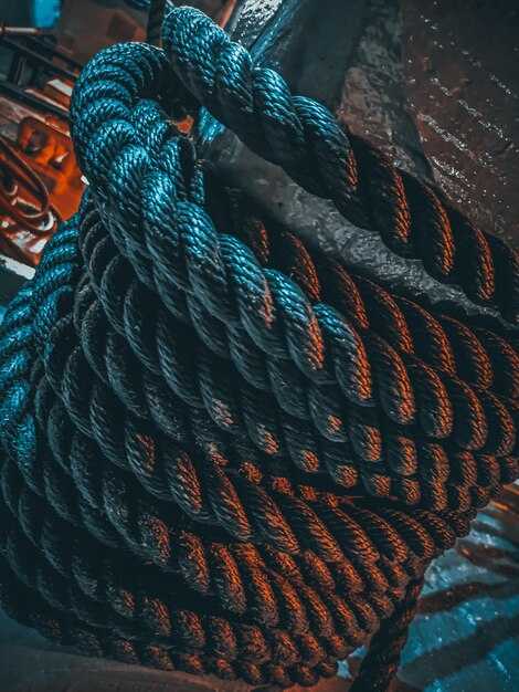
Start with a licensed, premium steel rope designed for heavy lifting and long service life. Assess condition and match rope to the load requirements, drum groove, and winch speed. A trusted provider with marine and industrial experience can tailor options for equipment you have on shore or aboard a boat. Ensure the rope is placed on a correctly grooved drum and lubricated with a compatible compound to reduce wear through lifted loads and cycles.
Two reliable families cover most needs: IWRC cores (independent wire rope core) provide strength and predictable wear, while fiber-core variants offer greater flexibility at lighter loads. For heavy-duty use, prefer a compact lay with a robust core and a 6×37 or 6×19 configuration that balances load capacity and bend resistance. Galvanized finishes protect against coastal spray and corrosion on shore installations and in boatyards. Some models carry model codes with abbreviations like ‘phan’–verify with the provider to ensure the code matches the construction you select. When you plan, start by mapping the combined height, reach, and drum diameter to your equipment, then placed the rope where it will see the most direct load path above the sheaves and gangways. These configurations were tested in field trials to confirm performance under real-world conditions.
Maintenance and operation tips: perform a daily check using a simple sticker on the winch cover to note rope condition, diameter, and any wire breaks. Keep a spare length ready; if a load triggers a partial rope failure, you can switch quickly without losing days of production. In marine environments, store rope away from bilge fumes and fuel spills; maintain proper air flow around the rope rack, and ensure the area around horns and lights on the winch remains clear. During summer, increase lubrication intervals and inspect the core more often as heat accelerates wear. Ensure the installation remains within licensed safety guidelines and that the crew spot-checks that alternators, battery feeds, and warning lights stay within normal ranges. Respect copyright and manuals from Capvina; use official PDFs for maintenance instructions and replacement parts.
Operational best practices: thread the rope through fairleads with generous radii and avoid sharp edges; keep rope trim and tension aligned to minimize wear. Place the rope with attention to the highest load paths above the shore-facing gangways and deck edges, and keep the work area above the boat’s deck free of clutter that could snag strands. Maintain a clear, safe work zone on start-up days and log any deviations in the maintenance notebook to ensure a smooth cycle through every shift. By coordinating with Capvina’s licensed provider network, you can tailor rope choices to seasons, duties, and specific equipment, delivering reliable performance whether you operate on shore facilities, in a shipyard, or on heavy machinery aboard a vessel.
Corrosion Protection: Coatings, Lubricants, and Maintenance Schedule
Apply marine-grade epoxy primer to all steel ropes and tubes, then seal with a polyurethane topcoat to achieve a 75–120 micron dry-film thickness. This two-layer system creates a durable barrier against salt spray and humidity, hence extending the life of ropes, tubes, and watercraft components in bilge and casing areas. Prepare surfaces by abrasive blasting to SA 2.5 or better, ensuring clean, dry metal before coating, and store coated parts away from heat until fully cured; this yields higher coating integrity across their service life.
Coating selection emphasizes a layered approach: zinc-rich primers on ferrous parts, a robust epoxy intermediate, and a UV-resistant polyurethane finish. For long-term immersion zones, target 60–100 microns on exposed steel and 75–120 microns on submerged sections. Use both water-based and solvent-based systems as appropriate, and schedule recoats based on exposure–roughly 12–18 months in saltwater and up to 36 months in sheltered inland uses. Include visual checks for cracks, blisters, and dulling; correct promptly to prevent deeper deterioration. Quản process entails documenting each coating cycle and keeping the content in a single maintenance file, with notes from technicians such as vinh and thanh to ensure consistency across their teams.
Lubricants protect moving parts without trapping moisture. On gimbals, locks, hinges, and bearing housings, apply marine-grade grease with corrosion inhibitors in a thin, even layer; avoid thick films that trap water. For ropes and their terminals, use lubricants formulated for synthetic fibers when applicable, and reapply every 3–6 months in dry environments or every 1–3 months where splash or immersion occurs. When servicing brass or brass-like fittings near a carburetor or road-use components, keep lubricants separate to prevent cross-contamination. Maintain light films to preserve higher efficiency and prevent residue buildup on tubes and casings, while preventing contact with water that precipitates deterioration of the fit.
El programa de mantenimiento proporciona una cadencia clara: una inspección a los 30 días posteriores a la instalación, luego revisiones trimestrales de los ensamblajes críticos y una evaluación profesional anual de la integridad del revestimiento. Mantenga un registro basado en el contenido que registre el grosor de la película, la humedad y cualquier signo de deterioro; adjunte una nota tipo carta para cada ciclo y compártala con el equipo. En entornos severos, implemente un ciclo más corto: de 6 a 12 meses para las nuevas capas y una cadencia de lubricantes de 3 meses; para aplicaciones más tranquilas, de 12 a 24 meses es suficiente. El objetivo es la misma protección en todos los componentes, incluidas cuerdas, tubos, revestimientos, sentina, líneas de flotación y equipos guardados en carretera, con los materiales adecuados seleccionados para cada material y escenario de uso, asegurando que estos y sus contenidos permanezcan protegidos en condiciones de mayor exposición.
Procedimientos Seguros de Enrollado, Elevación y Manipulación
Realice una verificación previa al enrollado y comience con el procedimiento: inspeccione el cable para detectar desgaste, verifique que la máquina, el molinete y los powerpacks estén dentro de las especificaciones, y asegúrese de que la estructura soporte la carga. Coloque el cable en el tambor en capas uniformes y márquelo con el código phuoc y la etiqueta 99-07 para su trazabilidad. Confirme que los puntos de anclaje estén listos y verifique que la cuna de envío o el soporte de costa estén seguros antes de cualquier movimiento.
Durante el enrollado, alimenta el cable en la dirección de la disposición del tambor, mantén una tensión uniforme y supervisa la temperatura del tambor. Mantén cada capa bien compactada y sin cruces; usa un esquema para verificar las trayectorias de la línea y evitar solapamientos. Si aparece una chispa en las superficies de contacto o en los cojinetes, detente, inspecciona las poleas y vuelve a verificar la alineación de las ruedas antes de continuar. Verifica siempre que los cables y las piezas estén limpios, secos y asentados correctamente.
El izado requiere una estiba correcta: sujete la carga con las eslingas y terminaciones adecuadas, inspeccione los cuernos de los ganchos para detectar desgaste y confirme que los pastecas y grilletes estén clasificados para la carga. Utilice ayudas tanto mecánicas como hidráulicas siempre que estén disponibles y coordine los grupos de potencia con el movimiento del pistón para evitar retrasos o sacudidas. Respete la carga nominal del molinete y evite cualquier carga lateral que pueda torcer el cabo o doblar la estructura; comunique cada paso con el operador a través de un mensaje conciso.
El manejo y el movimiento entre la costa y la embarcación exigen un anclaje claro y una planificación de la transición segura. Compruebe los dispositivos de anclaje, asegure las cuñas y mantenga la cuerda alejada de los herrajes del casco que podrían desgastar los cables. Al moverse entre el barco y la costa, asegúrese de que el molinete permanezca centrado y evite arrastrarlo por superficies ásperas. Para las operaciones de embarcaciones, mantenga un ritmo controlado y utilice una línea exclusiva para el atraque, con el fin de evitar la deriva descontrolada de piezas y equipos.
Documentación y respuesta: mantenga un esquema o diagrama operativo breve que muestre el recorrido del cable, el origen del molinete y los puntos de terminación. Registre la secuencia en el registro, señale cualquier desviación y envíe un mensaje corto al supervisor de turno que detalle el estado actual y los próximos pasos. Si las condiciones cambian, repita la verificación previa al enrollado y ajuste el procedimiento en consecuencia; a menos que los problemas se resuelvan rápidamente, detenga las operaciones para evitar daños a los cables, pistones o al tambor.
Mantenimiento e Inspección: Detección de Desgaste, Cables Rotos y Factores Desencadenantes para el Reemplazo de Cables
Establezca una regla base: reemplace el cable cada vez que la pérdida de diámetro o las roturas de alambres alcancen los umbrales definidos, y documente todo en el registro de mantenimiento. Esta regla permanece en vigor desde la instalación en adelante y siempre que haga pasar la línea por cargas y ciclos. Por lo tanto, implemente un requisito claro que vincule las métricas de desgaste con acciones factibles, no con suposiciones.
-
<strongComprobaciones visuales diarias: inspeccione si hay corrosión, aplastamiento, decoloración por calor, cocas, jaulas de pájaros y cualquier hebra deformada. Busque signos de exposición al agua cerca de accesorios, tuberías o soportes, y observe cualquier alfombra o rodillo que muestre un desgaste anormal.
-
<strongComprobaciones dimensionales y del estado del alambre:
- Mida el diámetro exterior en tres a cinco puntos a lo largo de un metro de cuerda utilizando calibradores o un medidor de cuerda; compare con el tamaño nominal para ese tamaño de cuerda. Si la pérdida promedio de diámetro excede el 3% para cuerdas de menos de 20 mm, o el 5% para diámetros mayores, marque para consideración de reemplazo.
- Cuente los alambres rotos en una longitud representativa (de un pie a 300 mm) de cada torón. Si detecta más de un umbral definido de alambres rotos en cualquier torón (normalmente alrededor del 10 % de los alambres en ese torón), el cable debe retirarse del servicio o redirigirse a tareas no críticas, según la gravedad del servicio.
- Compruebe si hay puntos duros, aplanamiento o protusión del núcleo aplicando una flexión suave y buscando secciones rígidas u opacas al tacto. Marque cualquier área sospechosa para una prueba formal o su reemplazo.
-
<strongIndicadores de daños e historial de servicio:
- Busque decoloración por calor, corrosión en los terminales, casquillos agrietados o hendiduras en la superficie del cable. Cualquier daño de este tipo requiere una evaluación inmediata.
- Observe los cambios en el comportamiento de la carga, los ruidos inusuales o la vibración durante el funcionamiento; estas señales justifican una prueba o una revisión de reemplazo parcial del cable.
- Registre el contexto de la instalación de la cuerda, incluyendo si ha funcionado en entornos sea-doo-can-am o andor, y si se utilizaron repuestos marinos en componentes como soportes o conectores.
-
<strongReemplazo de activadores y flujo de trabajo de decisión:
- La pérdida de diámetro que supere los umbrales establecidos desencadena una revisión de la decisión de reemplazo por parte del propietario del programa.
- Cualquier hilo que muestre múltiples alambres rotos en una longitud pequeña o un solo alambre gravemente fracturado cerca de un punto de conexión exige su sustitución o modificación, especialmente donde las cargas se concentran cerca de los elementos de conexión.
- La exposición visible del núcleo, el deshilachado o la corrosión severa cerca de las áreas de entrada de agua requieren una acción inmediata. Modifique el recorrido de inspección para evitar operar con un cable comprometido.
- En aplicaciones críticas, programe una prueba de todo el conjunto después de la sustitución para confirmar las vías de transferencia de carga, incluidas las conexiones colgantes o de tipo colgante y los soportes utilizados para montar el cable a la carga.
-
<strongDocumentación e integración del programa:
- Mantenga un registro de los tamaños, longitudes y configuraciones de montaje, incluyendo posiciones de los soportes y disposiciones de los colgantes. Haga un seguimiento cada vez que modifique los componentes de la jarcia o cambie a una longitud o diámetro diferente.
- Utilice un sistema de etiquetado que incluya números de serie, fecha de servicio y fecha de la próxima inspección; mantenga los registros por separado en el programa de mantenimiento para que las auditorías puedan verificar el cumplimiento de los requisitos de toda la flota.
- Incorpore datos de prueba de las ejecuciones de prueba y de las pruebas ajustadas en las evaluaciones continuas; correlacione los hallazgos de desgaste con el tiempo de carga y el tiempo de permanencia en la línea.
-
<strongMedidas de mitigación y acciones preventivas:
- Mantenga la cuerda alejada de bordes afilados. Utilice alfombras protectoras y barreras de agua donde sea posible, e instale poleas de rodadura con los radios adecuados para minimizar el desgaste de la superficie.
- Al enrutar la cuerda a través de tuberías o curvas cerradas, verifique que los radios de curvatura cumplan con las recomendaciones del fabricante y considere buscar rutas alternativas para reducir el contacto entre metal y cuerda.
- Instalar sensores de monitoreo inalámbricos en puntos críticos para proporcionar alertas tempranas de desgaste y activar estancias de mantenimiento o inspecciones aceleradas, especialmente en ubicaciones remotas o peligrosas.
-
<strongHigiene operativa y notas:
- Registre el estado de los hallazgos utilizando un formulario estándar y haga referencia a explicaciones inspiradas en la Britannica sobre la construcción de cuerdas para mejorar la comprensión de los mecanismos de desgaste por parte del equipo. Esta comprensión ayuda a los equipos a planificar las inspecciones con el mismo rigor que una pieza fabricada.
- Mantenga una sección dedicada para sea-doo can-am, marinespareparts y otros componentes especializados para asegurar la compatibilidad al reemplazar cuerdas o accesorios, incluyendo conectores y soportes utilizados en entornos marinos.
- Programar la reevaluación periódica de los umbrales de reemplazo como parte de los programas para toda la flota; actualizar los documentos de requisitos para que reflejen la experiencia sobre el terreno y las conclusiones en materia de seguridad.
-
<strongDisparadores de referencia rápida:
- Cables rotos visibles, dobleces, grietas o exposición del núcleo
- Pérdida de diámetro superior a 3-5% dependiendo del tamaño
- Racores o soportes extremos agrietados o corroídos
- Decoloración o daños por calor cerca de las tuberías o conexiones de agua.
- Ruido, vibración o ralentización de la carga inusuales durante el funcionamiento
Al adherirse a estas comprobaciones y activadores concretos, se reduce el riesgo de fallo y se prolonga la vida útil de la cuerda. Consulte siempre los programas específicos del fabricante de la cuerda y los requisitos de seguridad de su entorno, y considere las referencias técnicas de estilo Brittannica únicamente para una comprensión fundamental. Utilice los datos de prueba reunidos aquí para impulsar la renovación oportuna a una cuerda nueva y para optimizar el programa general de aparejo.