

 Achilles III Yacht General Arrangement Plans by Samuel White">
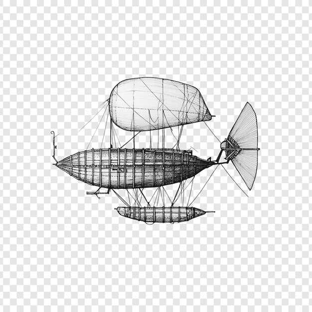
Review the Achilles III plans line by line to map deck zones, machinery spaces, and crew berths. The General Arrangement places the centerline as the spine, with the salon, navigation station, and mess grouped for efficient workflow. Use the scale bars and cross-sections to verify tank locations, hatch alignments, and shaft runs before any hands-on work.
For enthusiasts and labs focused on classic yacht design, the drawings offer clear notes on space flow and structural detail. desiring precision, many readers compare betas of hull frames and test different furniture layouts, playing the game of how rooms relate to the centerline and weather decks. The plan highlights guest areas and crew spaces to support a balanced experience for owners and their guests, aiding on-site enjoyment during refits.
niels and helens inspect the margins and sketches, enjoying how White’s lines convey stability and grace. desiring to learn how scale translates to real performance, they compare plan shifts across fore, mid, and aft zones, paying attention to the function of bulkheads and watertight doors. The documentation emphasizes practical decisions, not only noble aesthetics, which helps holders of the plans plan upgrades with clarity.
The drawings hint at environments beyond the berths: the lucier panels near the saloon catch light, the glassiness of portholes adds depth to the perceived hull form, and the deckwork shows the potential for helicopters on a pad, or light aircraft on hypothetical layouts. If you imagine badlands seas, the ballast notes provide guidance on trim and stability as winds gust and swell.
Holders who study Achilles III drawings can reproduce the alignment in scale models, test furnishing in center sections, and compare with other Samuel White plans to learn design continuities. This approach keeps you enjoying the process, whether you are restoring a classic or planning a display, and supports a measured, hands-on workflow for those who remain curious and hoppy about precise lines.
Practical guide to reading Achilles III plans and their link to the Whydah project
Read the sheets simply by focusing on baseline anchors, frame lines, and notes.
Begin with a simple move: identify the anchored baseline on the Achilles III plan set, then verify the scale against known Whydah measurements. This anchored start creates a safe reference for any inspection, and keeps your workflow predictable as you compare data sets.
Key elements to read on each sheet:
- Frame stations and hull lines: locate the frame numbers, vertical positions, and the keel alignment; ensure the lines are braced to the same baseline across sheets.
- Notes and documentation blocks: read the stamped dates, revision marks, and the signatures of the team to gauge consistency; these documents hold the traceability of changes.
- Material lists and bonds: check bracing, fasteners, and plate thickness; compare with the Whydah project material table to spot mismatches in bonding patterns.
- Financing and plan context: note any financing constraints or plan correlations that explain equipment selections and planned work steps; this makes it possible to judge feasibility of the restoration path.
- Technical details: bracing, deck details, and hull curvature; use computers to run simple checks like line-of-curve continuity or station spacing; this prevents misreads before moving to fabrication steps.
Insights from volunteers and scientists emphasize keeping a full set of references: documentation, tools, and machines used to measure and record. In practice, keep the original documents and create parallel digital archives across mediums, so you can read anywhere and review changes quickly. When you see lines that feel inconsistent, pause and compare with Whydah records; this is where the science of reconstruction holds up against new findings. Team routines often include casual breaks with sandwiches on the table and hobbies that keep focus steady.
Team roles guide the workflow: zachar logs revisions; jacob handles the documentation updates; ross, a scientist, cross-checks bracing layouts against the vessel’s known geometry. Their disciplines create a robust chain of custody for plans and reduce risk of misinterpretation.
Practical checklist to keep on hand:
- Confirm anchored baseline and scale on the current sheet.
- Mark the frame numbers and note any deviations from the standard plan.
- Cross-check with Whydah references for critical sections such as transom, stern frames, and deck-spars.
- Verify material lists, bond details, and fastener patterns; note any conflicts and record them as action items.
- Store both the original documents and a searchable digital copy; ensure tools and machines used for measurements are logged.
- Prepare a concise summary that links each plan page to a Whydah reference; this strengthens the justice of a consistent interpretation.
- Schedule regular reviews, using a pace that accommodates new data and avoids rushed conclusions.
Done properly, the process keeps plans clear, data traceable, and the comparison with the Whydah project precise. The result is a full, credible understanding that informs decisions on financing, construction readiness, and long-term stewardship of the Achilles III heritage.
Identify the main compartments and their functions in the Achilles III general arrangement
Begin with the engine room and services, because quick access to the generator, pumps, electrical switchboard, and aero ventilation keeps the vessel operational and reduces downtime. Creativity really shines when these spaces are clearly defined and labeled.
Forepeak houses the anchor chain locker, windlass, and forward equipment; a separate bilge keeps water away from living spaces and supports easy maintenance.
Skiff storage sits at the transom, with a hang-ready area to secure the skiff when not in use.
Chart table, navigation gear, and comms rack sit in the designated navigation area; proper light and fresh-air supply cool the space during long watches.
Galley and crew mess are provided with a compact triangle, refrigeration, and waste handling; kindly layout keeps crew energized during dawn watches.
Main engine room houses propulsion, exhaust, and cooling; attached pipes and hatches speed routine maintenance.
Electrical room stores batteries, switchgear, and the main distribution panel; ensure redundancy and easy access to controls.
Fuel and fresh-water tanks lie in strategically placed compartments below deck, kept within trim limits; minute-level monitoring avoids shifts in stability.
Lazarette behind the engine room offers tool lockers, spare parts, and rescue gear; these compartments reduce downtime and improve response time.
Crew bunks and heads are separated from machinery vibrations; a separate hold area stores personal gear for long passages.
Backstay and rigging spaces align with deck plan; access to chainplates and spar fittings keeps rig checks efficient.
Dedicated pump room and workshop space provide the diverse maintenance tasks; tools, parts, and scripts for routine work are attached within reach.
Design notes from dunkiel and richter guided the partitioning; canadian input entered at the dawn phase, began refining layouts with arwen, aiming for magical efficiency and a thrilled crew.
These compartments together deliver a better, more predictable operation; the Achilles III general arrangement supports a range of missions and makes daily routines smoother.
Analyze the deck plan: mast steps, hatches, deckhouses, and access routes
Start by aligning the mast-step footprint with the foredeck and the forward deckhouse wall to create a solid foundation that transfers rig loads predictably. This reference point guides the layout of each hatch, deckhouse door, and access route, so the plan remains stable under hitting waves and heavy gusts.
Map every hatch to its interior function, keeping each opening close to the hall and galley where the oven and beverage storage live. Plan watertight seals and drainage so a splash in clouds doesn’t flood the space, and position weatherproof coamings to support quick, reliable operation for crew and guests alike.
Deckhouses sit on reinforced airframes that resist flex and torsion. Ensure doors do not clash with the mast step line, and provide adequate ventilation and daylight through skylights or ports. Use rounded edges on coamings to reduce snagging lines and improve safety during busy deck activities.
Design access routes to prioritize smooth crew flow from the cockpit to the helm, nav station, and the hall areas, while preserving direct paths to cabins and the galley. Keep secondary routes clear to avoid bottlenecks during shifting shifts or emergencies, and install clear signs so changes in layout are immediately obvious to everyone, including visiting students.
- Mast steps: verify footprint alignment, step height, and non-slip tread; ensure a direct line to the mast partner and forward bulkhead.
- Hatches: specify diameter, coaming height, gasket type (neoprene or silicone), drainage, and locking hardware; ensure redundant hatches for emergency egress.
- Deckhouses: confirm width and length relative to deck curvature; place doors for quick access to cabins and the galley; verify ventilation paths and seal integrity.
- Access routes: establish primary pathways from the cockpit to the wheel, nav area, and crew spaces; add secondary routes to the aft deck and galley; test with a crew of six to confirm flow and safety.
- Mast steps: record offset from centerline, acceptable tolerances, and material specs; plan for rounded corners on structural members to reduce snag points.
- Hatches: document dimensions, coaming height, gasket material, and hatch locking methods; ensure consistent closure force for all openings.
- Deckhouses: list mass, support points on airframes, door clearance, and ventilation capacity; verify alignment with interior stowage like pantry, beverages, and crew hallways.
- Access routes: map headroom, ladder angles, handrail heights, and anti-slip criteria; check in varying sea states and with equipment in use (rented gear or otherwise).
Continue with a disciplined problem-solving approach: note changes in the plan, sign off adjustments, and keep a running mind-map that the team–william, brendan, stefan, daniel, evan–uses during reviews in vermont with the engineering students. Use amine-based sealants judiciously on deck joints where necessary, then test water-tightness after simulated spray. The result should feel musical in its rhythm: each step, each hatch, each doorway aligns with the deck’s function, supporting a safe, efficient flow for all hands on board, and keeping the mission-ready process steady for the league of tests and blue-water adventures. This approach ensures prices stay reasonable, with clear notes when buying or renting equipment, and a transparent sign-off that reflects minds focused on practical, tangible improvements rather than theory alone.
Review crew quarters, mess, and officer accommodations for daily life and workflow
Prioritize modular crew quarters with privacy zones and a compact, functional mess to support quick transitions between watches.
Align the lifecycle planning for furnishings: acquired wardrobes, hang lines for uniforms, and modular bunks. Parker, Erik, and Dennis oversee routine checks, verify inventory, and adjust layouts. A sigma lighting plan and strom power distribution support night operations, with rovs monitoring alongside deck systems during eastern ports and short hops. The setup accommodates minor adjustments and coaching sessions, with programs running on onboard software to verify readiness during each watch cycle.
| Zone | Kapacita | Klíčové vlastnosti | Workflow Benefit | Upgrade Recommendations |
|---|---|---|---|---|
| Crew Quarters Cluster | 8–12 crew | modular bunks with privacy curtains, personal lockers, bedside lighting | reduces noise transfer, supports quick check-ins during shifts | acoustic panels, small 1-person work desks, detachable privacy screens |
| Mess | 18–24 seats | adjacent galley, servery, clear dining flow | streamlines meal service and reduces congestion at peak times | staggered dining slots, modular seating to reconfigure for briefings |
| Officer Accommodations | 4 cabins + en-suite | desk, wardrobe, small lounge, window, climate control | facilitates private planning and rest during watches | soundproof doors, optimized storage, enhanced outlets |
| Recreation and Pool Deck | shared lounge and pool area | pool, seating, small gym corner | supports downtime and crew morale | resilient flooring, anti-slip surfaces, quick-dry finishes |
| Coaching/Training Corner | 1 room | VR/AR coaching tools, whiteboard, bench | facilitates rapid skills refresh and safety briefings | integrate with onboard software, connect to training programs |
An intermediate maintenance cycle keeps the crew spaces clean and ready for audit. This supports ongoing performance and reduces friction during port calls, while alongside coaching strengthens daily routines and teamwork in eastern ports and during long runs between stops.
Read Samuel White’s draughting conventions: scale, line types, and sectional references
Begin this study with a single, fixed standard: use 1:50 for the Achilles III general arrangement drawing, with 1:25 reserved for major sections and 1:16 for critical machinery zones. Mark each sheet with a clear scale bar and a visible note that reads “Scale 1:50” to prevent mis-reading elsewhere. Maintain this consistency across the full set to keep the lines and sections aligned, especially where deck lines intersect framing.
Apply a three-tier line system: hull outline in bold solid 0.6–0.7 mm; waterlines and deck edges in 0.35–0.5 mm; and fine detail lines in 0.25 mm. Use hidden edges as short-dashed lines and centerlines as long-dash with short dashes; for section lines, use a bold solid line with hatch pattern to show material. Place dimension lines close to features but offset from the main outline to avoid clutter.
Sectional references are labeled with letters A-A, B-B, C-C and tied to stations along the keel. Show frames and stations at major intervals, typically every seven frames on longer hulls, to keep the cross-sections legible. In Samuel White conventions, the sectional drawings sit beneath the plan view on the sheet and align with the frame numbers; always indicate the cut orientation and the view direction.
To connect the practice to archives used by builders across regions, note that shawn and travis led a careful review in february; teams in connecticut and the northeast contributed, with juniors like elche, lowe, mann, and mason drawing notes for small details. The beashel crew and others kept the ones with the family touch focused; analytics and electronics notes proved invaluable in testing loads for the structure, and the calls to engineers sometimes referenced explosive bolt patterns that were later stopped in revision. The crew devoted time to teach younger draftsmen the rules of line weights and sectional calls. The beauty of Samuel White’s approach remains remarkable elsewhere, as the seven standard conventions are repeated across sheets seven times and cover scale, line types, and sectional references with clarity; this makes the historical plan an invaluable resource for modern restorations and for curious enthusiasts.
Assess how Achilles III plans inform reconstruction or model-building of Sam Bellamy’s Whydah
Start with a concrete recommendation: use Achilles III plans as the baseline for reconstructing the Whydah, adopting a 1:48 frame grid and mapping hull stations to period references. Prior research and your available resources define clear goals for hull curvature, beam, deck heights, and crew spaces; this baseline provides a practical starting point. Transfer Achilles III lines into a Whydah-compatible grid, and validate the mapping against Whydah measurements and surviving artifacts. Maintain a disciplined audit trail so decisions stay anchored in verified data rather than conjecture.
Build clay prototypes for internal frames and deck modules to test spacing and fairing. Use rotorcraft-grade alignment checks to verify station offsets, then carry those measurements into small-scale plank tests. Maintain a small, focused team to keep the workflow practical and aligned with the prior plan. These tests reveal where Achilles III data must be adjusted to fit the Whydah’s stern configuration and rigging patterns, ensuring only verifiable facts enter the model.
Document a set of recipes for planking sequences and fairing compounds; test with clay mockups to verify curvature and underwater hull fairness. Use mustard-colored markings to differentiate deck levels during trials. This approach helps ensure the hull exterior shows the correct curvature when aligned with the keel and frames carried into the model, preventing drift in gunwale alignments.
Příjem dat z archivů a muzeálních sbírek posiluje věrnost. Zkontrolujte detaily Achilles III s měřeními specifickými pro Whydah: výšky gunwal, otisk paluby, pozice zámečnických kroků. Doyleovo vedení a pozornost řídí pracovní tok; tam tým udržuje přísnou auditní stopu, která dokumentuje každou úpravu. Některé klíčové reference se nacházejí v námořních knihovnách v Bosně nebo v regionálních archivech v blízkosti letištních uzlů, s digitalizovanými kopiemi dostupnými pro ověřování rozměrů, počtů a armatur. Toto povědomí o zdrojích pomáhá řídit zdroje a vyhnout se mezerám. V terénních podmínkách zůstává pitná voda dostupná.
Zaměřte se na kritické roviny: kýl, středové rámy a záďovou konstrukci; udržujte zarovnání palub a linií gunwale, abyste zajistili pohodlnou manipulaci na stolním pracovním povrchu. Použijte malou posádku a plánujte úkoly tak, aby se zdroje přenášely efektivně a pokrok zůstal viditelný. Pracovní postup zůstává ukotvený Doyleovým vedením a pozorností věnovanou každému datu, čímž zajišťuje jasnou cestu od Achilles III k použitelnému segmentu Whydah.
Dobrodružství motivuje práci; tento překlad Achilles III do modelu Whydah vyžaduje hluboké porozumění geometrii rámu, uspořádání paluby a uspořádání lana. Začněte měřeními a poté zasílejte aktualizované soubory týmu, jak se přidávají moduly; některé aproximace se objevily v prvních návrzích, ale byly opraveny. Použijte sadu nástrojů úrovně Gulfstream pro dokumentaci, ale udržujte proces praktický a udržovatelný. Dokončete modulární model trupu v měřítku 1:48 s testovacími palubami, které lze sdílet s ostatními, a zajistěte tak, aby projekt zůstal transparentní a reprodukovatelný.